If you would like to play around with a circuit simulation tool here is a freeware tool by LinearTechnology to start with.
You may download the program from here.
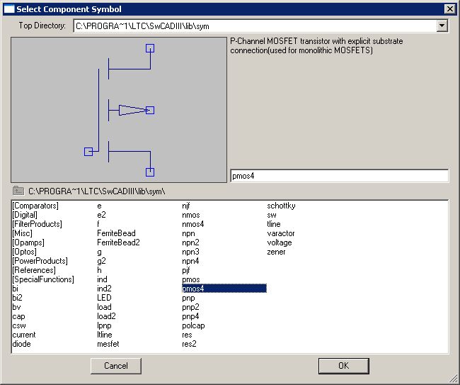
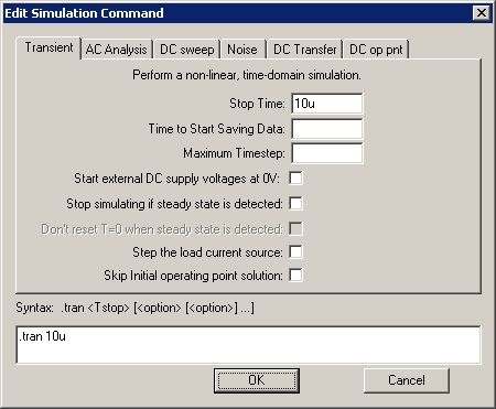
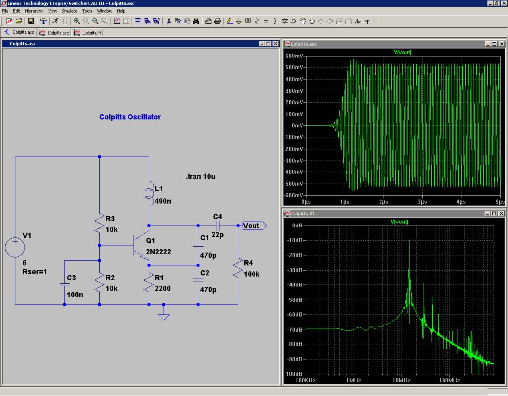
It is easy to work with. Just enter your schematic, select the simulation type and see what signals you get on the different nodes. The following screen shots show some of the menues and a simulation of a colpitts oscillator.
From the help file:
Preface
Do we need another SPICE?
Analog circuit simulation has been inseparable from analog IC design. SPICE simulators are the only way to test circuitry prior to integration onto a chip. Further, the SPICE simulation allows measurements of currents and voltages that are virtually impossible to do any other way. The success of these analog circuit simulators has made circuit simulation spread to board level circuit design. It is easier in many cases to simulate rather than breadboard, and the ability to analyze the circuit in the simulation for performance and problems speeds the design of well-understood, robust circuits.
Given the number of commercially available SPICE simulators why should a new simulator be written? Because certain analog functions are extremely difficult to simulate with commercially available SPICE simulators. Switch-mode power supplies have fast high frequency switching square waves as well as slow overall loop response. This means simulations must run for thousands to hundreds of thousands of cycles in order to see the overall response of a switching regulator. Commercially available SPICE's simply take too long for this to be a useful simulation method. Simulation times for a switch-mode power supply must be in minutes not hours for a simulator to be useful.
There have been analog circuit simulation methods that have shown some success in speeding up switch mode power supply simulation but at a cost of making simplifying assumptions which don't allow arbitrary control logic and fully simulate the complexity of the switching waveforms. A new SPICE with integrated logic primitives that perform the switch mode control provides a better answer. It can give fast simulation times, yield detailed waveforms, and still allows the flexibility for arbitrary circuit modifications.
SwitcherCAD III is a new SPICE that was developed for modeling board level switching regulator systems. Incorporated into the new SPICE are circuit elements to model practical board level components. Capacitors and inductors can be modeled with series resistance and other parasitic aspects of their behavior without using sub-circuits or internal nodes. Also, a simulation circuit element was developed for power MOSFET's that accurately exhibits their usual gate charge behavior without using sub-circuits or internal nodes. Reducing the number of nodes the simulator needs to solve significantly reduces the computation required for a given simulation without compromising the accuracy or detail of the switching waveforms. Another benefit of these new simulation devices is that convergence problems are easier to avoid since they, like the board level component the model, have finite impedance at all frequencies.
Modern switch mode power supplies include controller logic with multiple modes of operation. For example, devices may change from pulse switch modulation to burst-mode or to cycle skipping depending on the circuit's operation. An original new mixed-mode compiler and simulator were written into SwitcherCAD III that allows these products to be realistically modeled in a computationally fast manner.
There are currently approximately seven hundred Linear Technology products modeled in SwitcherCAD III. The program is freely downloadable from the Linear Technology website and is a high-performance general-purpose SPICE simulator. Included are demonstration files that allow you to watch step-load response, start-up and transient behavior on a cycle-by-cycle basis. Included with the SPICE is a full-featured schematic entry program for entering new circuits.
SwitcherCAD III is designed to be used by three different types of design engineers: those who know what they're doing, those who think they know, and those who are sure they know absolutely nothing about switching regulator design. The experienced designer needs a "what if" program that allows him to quickly alter aspects of a circuit to find an optimum design. The neophyte needs a cookbook approach that yields a reliable design based on the simplest of inputs. The "loose cannon" designer needs a program that will allow him to exercise his free will, but will be intelligent enough to alert him to fatal design flaws.
To that end, we made SwitcherCAD III an extremely flexible "what if" electronic design tool that has warning labels when things are getting out of hand. We designed the program to have a complete initial design cycle based only on the essential inputs of voltage and power requirements. This allows the terrified designer to start with a working circuit, permits the experienced designer to have unlimited fun changing things, and, we hope, provides enough safeguards to prevent bad designs.
Please be aware, however, that SwitcherCAD III is not intended as a total solution. It is only a tool to ease the design procedure, which must also include breadboarding and testing. Use common sense with the results obtained from simulation.